Electronic scale body installation sequence 12 instructions
The accuracy of the weighing should also be checked regularly after the electronic scale has passed the test. The preheating of the weighing display is generally 30 minutes. The power must be cut off after the stop of work. It is not allowed to unplug the cable plug when the weighing indicator is powered. The personnel who manage the car floor scale must read the operating instructions. When the vehicle is on the weighing platform, the vehicle speed is lower than 5km/h, then slowly brake, and the vehicle starts to measure after stopping. When the vehicle is on the weighing platform, it should be straight as far as possible to stay in the center of the weighing platform.
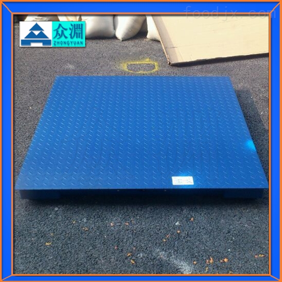
Electronic scale body installation sequence 12 items Description:
(1) Unpacking: Try to unpack the tool at the installation site. When unpacking, be careful not to damage the components inside the box.
(2) Inventory: Check the parts according to the packing list. When the equipment is not installed immediately after unpacking, all the parts should be put together for storage to prevent loss.
(3) Check that the basic dimensions conform to the dimensions specified in the car floor map.
(4) Mapping the basic centerline and related position lines according to the drawings.
(5) Install the base according to the assembly drawing.
(6) Check the installation position of each sensor with a ruler to ensure that the diagonal tolerance is not more than 3mm, and the tolerance of length and width is not more than 2mm.
(7) Put the gasket under the base and adjust the height and level.
A. The height difference between the planes on the bases is not more than 1 mm.
B. The horizontal error of the plane on the base is not more than 1/100.
(8) Lifting the carrier.
(9) After adjusting the position of the carrier, tighten the nut at the joint.
(10) Wire according to the wiring diagram.
(11) Adjust the longitudinal and lateral limit bolts so that the gap between the bolt head and the baffle is no more than 4 to 5 mm.
(12) The periphery of the base is fixed by cement coagulation to enrich the space under the bottom plate.
Insulin Syringes Needle,Disable Syringe,Monoject Syringe,10 Ml Syringe
FOSHAN PHARMA CO., LTD. , https://www.foshanmedicine.com